Author: Marcus von Cube <marcus@mvcsys.de>.
The ReMem is a memory expansion board for the Radio Shack TRS-80 Model 100 laptop computer and its relatives. It is designed by Stephen Adolph and has its Internet home here. Useful information about the Model 100 and many links can be found on the Model 100 Users Group web site. If you have a Model 100 and do not know if you want to install a ReMem, you can play around with VirtualT, a Model 100 emulator that emulates ReMem as well.
This document is an extension to Steven's installation instructions. My system has a mainboard that is suffiently different from what he describes and thus deserves special treatment. In a few words: The installation is a little more demanding but it can be made to work.
Most pictures in this document are available in a higher resolution by simply clicking on them.
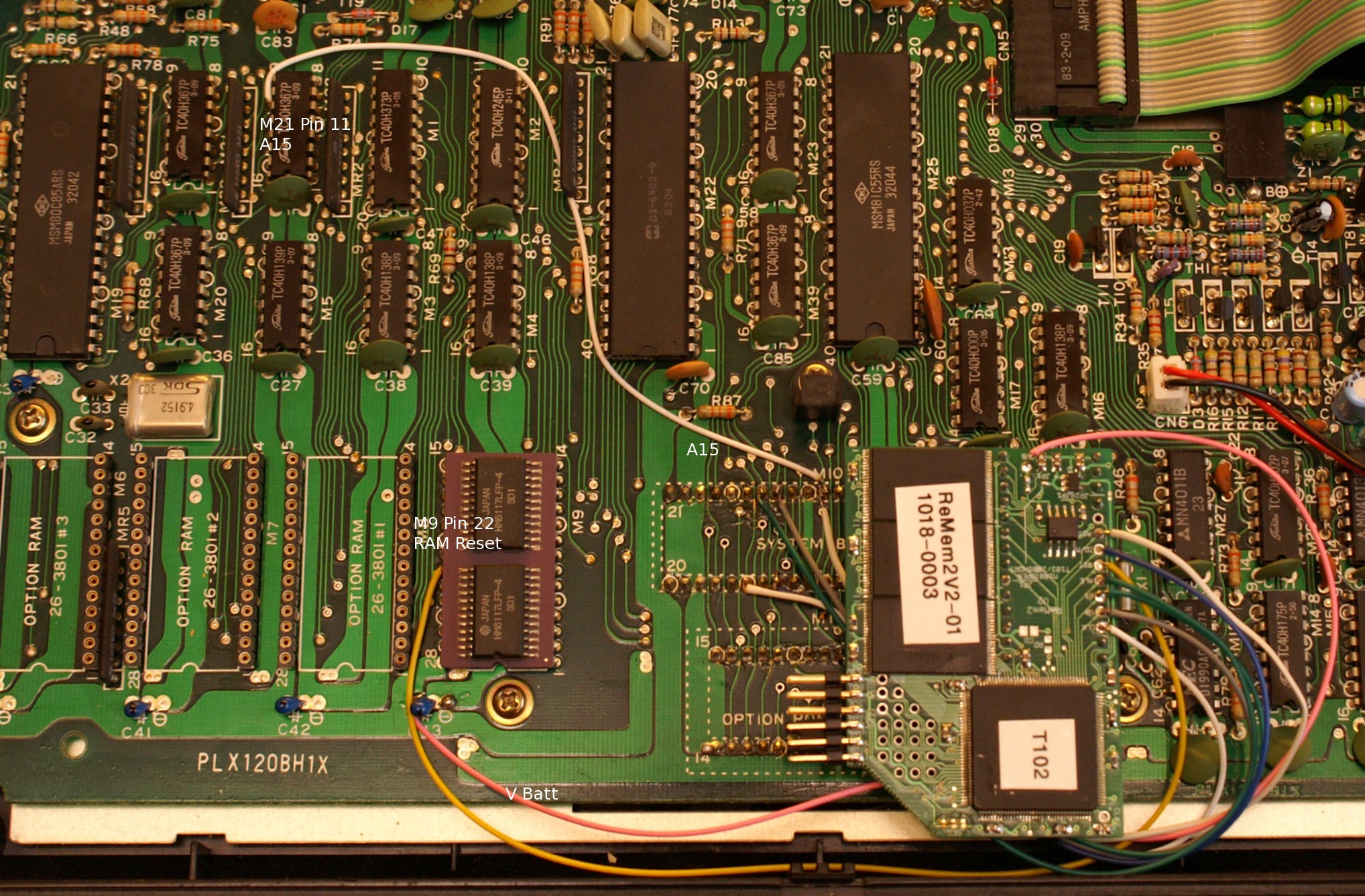
Here is a view of the mainboard:
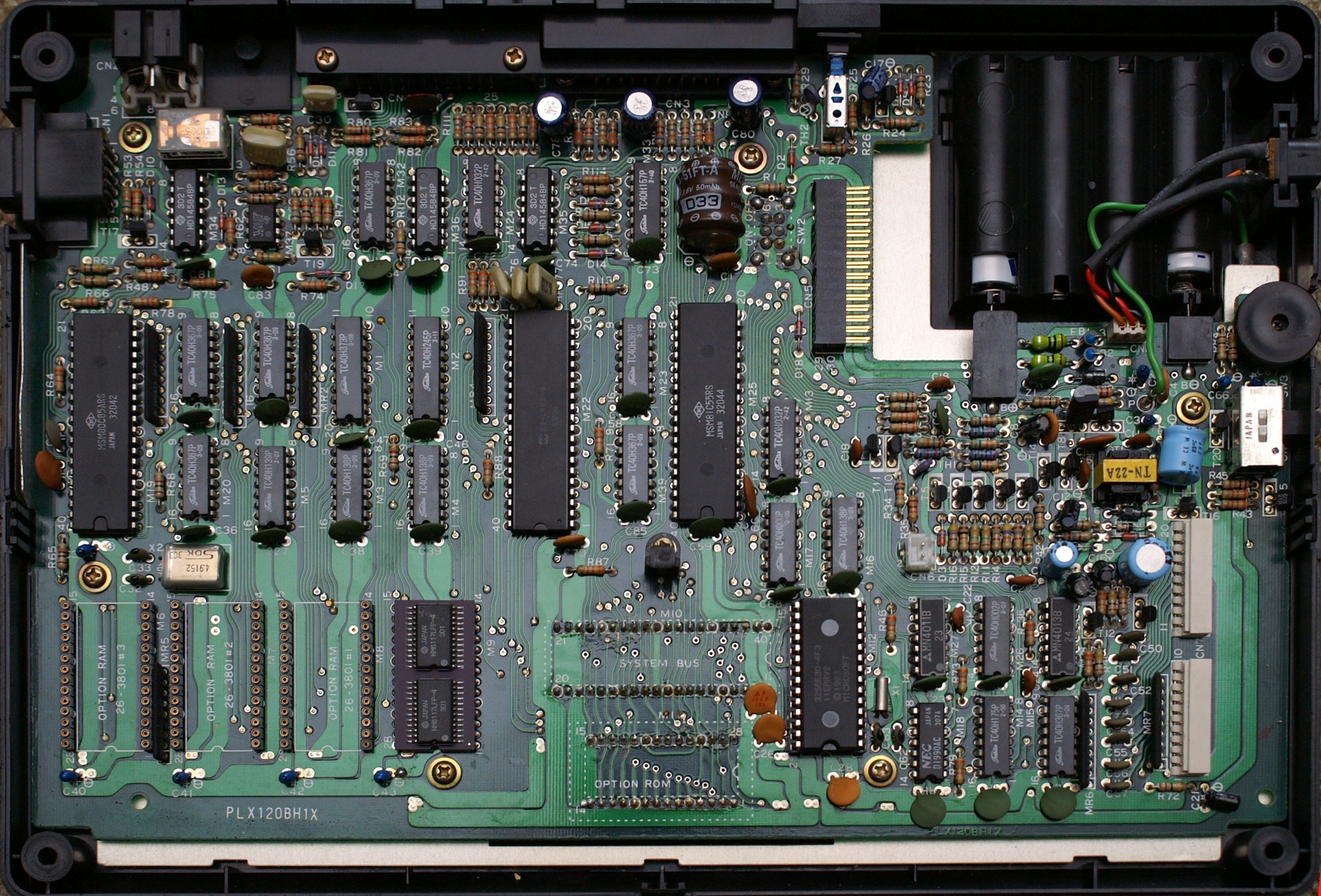
The type is PLX120BH1X as can be seen in the lower left corner. If your mainboard looks different, you can skip these instructions but you might still want to have a look at the software at the end of this document.
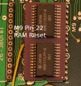
The original instructions describe where to find the signal RAM Reset but I couldn't find the resistor mentioned. After a while and a look in the schematics, I realized that it would be easiest to pick the signal directly from a memory socket. It is on pin 22 on any of the build in RAMs. I've connected the (yellow) wire directly to the module M9.
The address line A15 must be seperated from the RAM address decoder M5 and the decoder input must be pulled high in order to disable the built in memory module which cannot be pulled out because it is soldered in. After some search I found the trace to cut: it is on the backside. So you have to pull the motherboard out. Unfasten all six screws. The distance knob is near the system bus socket and must be reattached in the same orientation. It makes sure that there is enough headroom between mainboard and keyboard.
Now turn the board over and find M5:
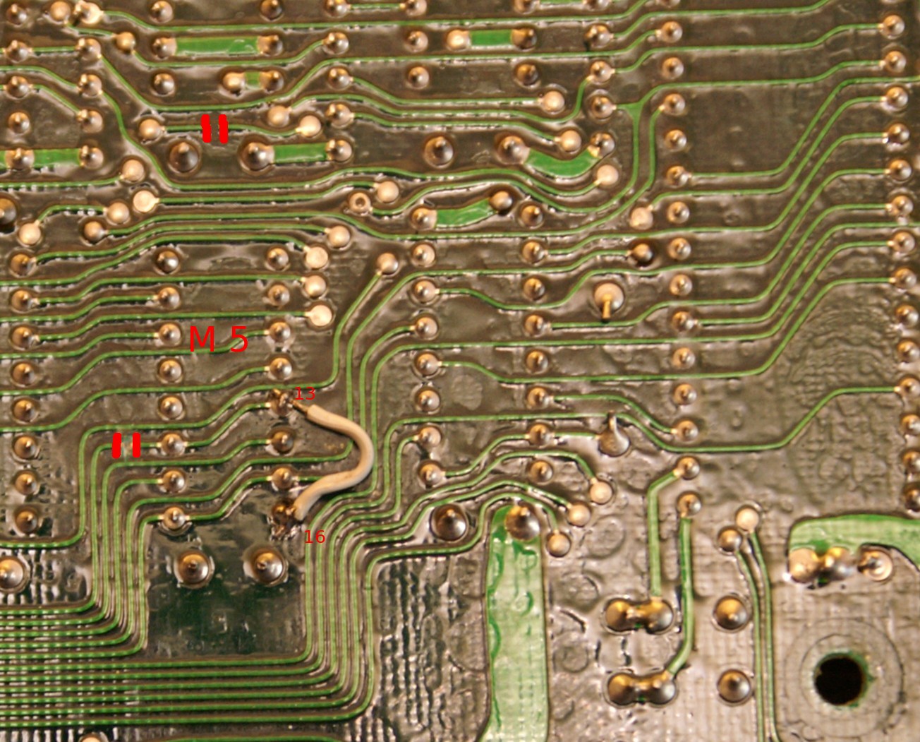
The big IC to the right is the CPU. Use a sharp knife to cut the traces as indicated in the picture. Bridge pins 13 and 16 of M5 to pull the input to high. We could have used a resistor here, too. Now turn the board over and fasten it. Be careful with the reset switch which must be fiddled through its hole in the rear of the case. The distance rings around the screw post should go were they were: My machine had none near the option and expansion sockets.
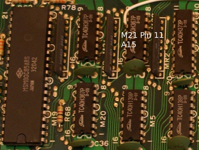
Now solder a wire to pin 11 of M21 and wire it to pin 31 of the system bus. From there a wire goes to the ReMem as by the original instructions.
Now you can install the ReMem module with all its wiring. You need to connect ALE from the option ROM socket, too. This is how it looks after installation:
When you turn over the keyboard, you see a small plastic sheet near the front of the case that stabilizes the keyboard and keeps it in position. It looks as if this sheet was causing pressure on the ReMem and influencing its operation. So I took it to my workbench to cut some material out:
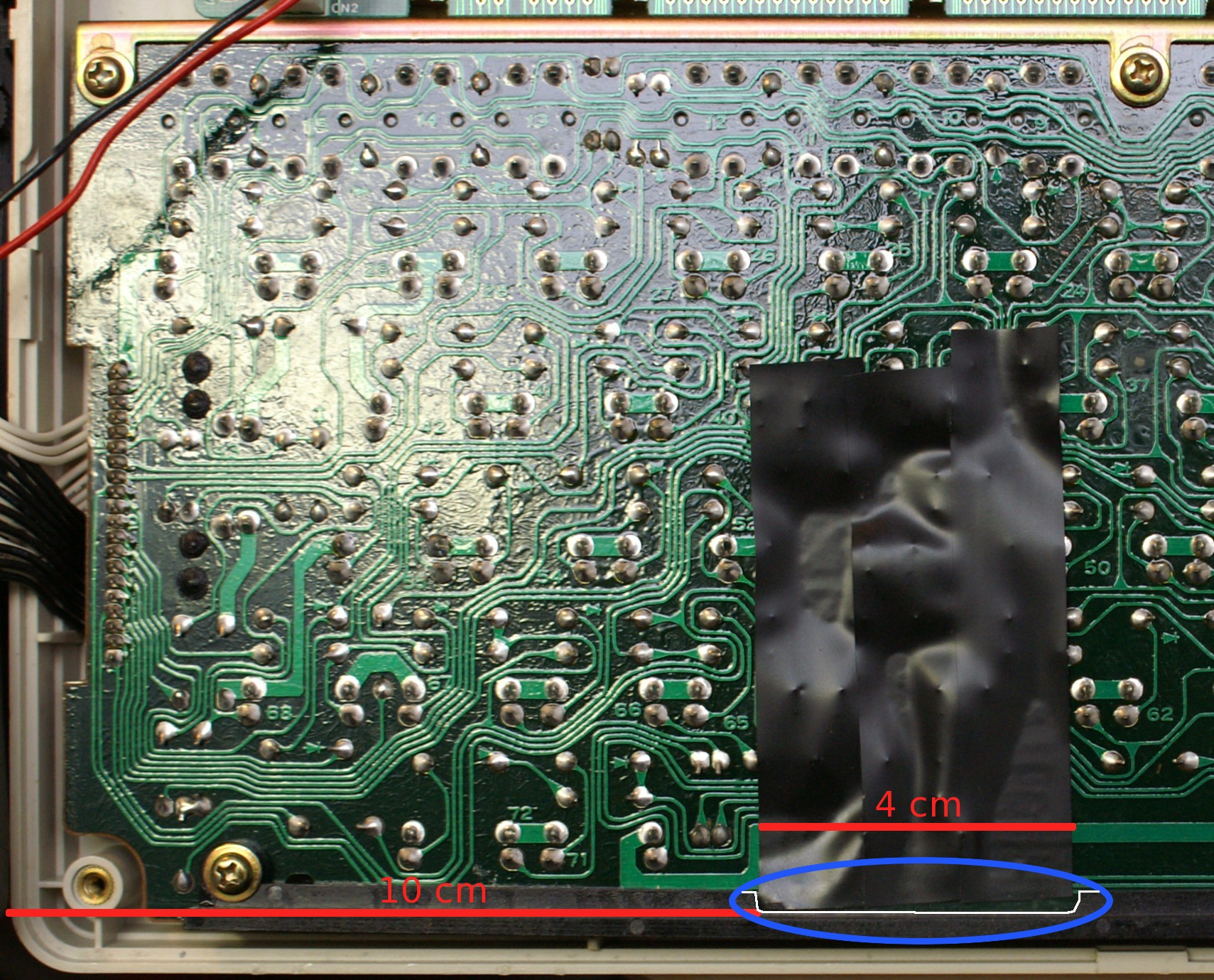
The tape adds some electrical protection between the keyboard and the ReMem board.
That was it. At the moment, everything seems to work fine.
10 ' Option ROM selector for ReMem
20 H$="Select option ROM for MAP"
30 CLS:PRINT H$
40 INPUT"Map (1-8)";M:IF M=0 THEN END
50 IF M<1 OR M>8 THEN 30
60 PRINT@94,"(0: Read current value)";:PRINT@80,;
70 INPUT"ROM (0-8)";R
80 IF R<0 OR R>8 THEN 60
90 CLS:PRINT H$
100 ' Compute sector and enable map I/O
110 S=2+4*(M-1)
120 PRINT "Map:";M;TAB(8);"Map sector:";S
130 OUT 112,INP(112) OR 4 'enable
140 ' Select read or update
150 IF R=0 THEN GOSUB 1000 ELSE GOSUB 2000
160 OUT 112,INP(112)-4 'Disable map I/O
170 PRINT"Again";:GOSUB 11000
180 IF YN THEN 30
190 END
1000 ' Read current value
1010 OUT 97,S
1020 L=INP(99):H=INP(99)
1030 HL=H*256+L
1040 HE=HL:GOSUB 10000:PRINT"First word: ";HE$
1050 R=INT((HL AND 2047)/32)
1060 PRINT "Option ROM #";CHR$(R+48)
1070 RETURN
2000 ' Set new value
2010 PRINT "Option ROM #";CHR$(R+48)
2020 HL=32*R+28672 '7000h
2030 HE=HL:GOSUB 10000:PRINT"Map data: ";HE$;
2040 HE=HL+31:GOSUB 10000:PRINT"..";HE$
2050 PRINT"OK";:GOSUB 11000:IF YN=0 THEN RETURN
2060 OUT 97,S
2070 FOR I=0 TO 31
2080 H=INT(HL/256):L=HL AND 255
2090 OUT 99,L:OUT 99,H
2100 HL=HL+1
2110 NEXT I
2120 RETURN
10000 ' HEX-Output HE->HE$
10005 IF HE=0 THEN HE$="0":RETURN
10010 HE$=""
10020 DD=HE AND 15
10030 IF DD<10 THEN DD$=CHR$(DD+48) ELSE DD$=CHR$(DD+55)
10040 HE$=DD$+HE$
10050 HE=INT(HE/16)
10060 IF HE=0 THEN RETURN
10070 GOTO 10020
11000 ' Y/N prompt
11010 PRINT" (Y/N)? ";
11020 YN$=INPUT$(1)
11030 YN$=CHR$(ASC(YN$)AND223) 'upper case
11040 YN=INSTR("NYJOS",YN$)-1
11050 IF YN<0 THEN 11020
11060 IF YN THEN YN$="Y":YN=-1:PRINT"Yes" ELSE PRINT"No"
11070 RETURN
You can query the current setting by entering 0 as the ROM number. I have yet to play around with flashing other ROM images. So by now, all maps have TS-DOS configured as ROM. Be careful: LDMAP.BA with the default MAP100.CO file will revert to the default settings!
My second attempt at ReMem programming solves the bootstrap problem: After loading all the utilities in one map, how can I get them in all the other maps? After initialization a map is clean: just the default applications from ROM are installed. Here is the solution, just copy and paste the code in a file named MAPDUP.DO and download it to your Model 100:
10 ' Duplicate a ReMem MAP's RAM
20 H$="Duplicate a MAP's RAM"
30 CLS:PRINT H$
40 CR=INP(112)
50 IF (CR AND 1)=0 THEN PRINT"Not in MMU mode!":END
60 CM=((CR/8)AND 7)+1
70 PRINT"Current map is";CM
80 INPUT"Source map (1-8)";SM:IF SM=0 THEN END
90 IF SM<1 OR SM>8 THEN 30
100 PRINT@120,;:INPUT"Destination map (1-8)";DM
110 IF DM<1 OR DM>8 OR DM=CM THEN 30
120 CLS:PRINT H$
130 ' Compute MMU sectors
140 CS=0+4*(CM-1) 'ROM space
150 SS=1+4*(SM-1) 'RAM source
160 DS=1+4*(DM-1) 'RAM dest
170 ' Read MMU data source/dest
180 DIM MM%(31,1)
190 OUT 112,CR OR 4
200 J=0:OUT 97,SS:GOSUB 1000
210 J=1:OUT 97,DS:GOSUB 1000
220 ' Prepare ML
230 BA=64704 'FCC0
240 ' Save current mapping (2K)
250 OUT 97,CS
260 FOR I=0 TO 3
270 POKE BA+I,INP(99)
280 NEXT I
290 READ L 'bytes in ML
300 FOR I=0 TO L-1
310 READ B
320 POKE BA+8+I,B
330 NEXT I
340 ' Copy loop
350 FOR I=0 TO 31
360 PRINT@80,"Copying";I+1;"KB";
370 ' Set source address
380 L=MM%(I,0)AND 255:POKE BA+4,L
390 H=MM%(I,0)\256:POKE BA+5,H
400 ' Set destination address
410 L=MM%(I,1)AND 255:POKE BA+6,L
420 H=MM%(I,1)\256:POKE BA+7,H
430 ' Call ML routine
440 CALL 64712,CS 'FCC8 A=MMU sector
450 NEXT I
460 OUT 112,CR
470 END
1000 ' Read MMU data
1010 FOR I=0 TO 31
1020 L=INP(99):H=INP(99)
1030 MM%(I,J)=H*256+L
1040 NEXT I
1050 RETURN
65000 ' MAPDUP.BIN
65001 DATA 50
65002 DATA 243,79,211,97,6,4,33,196
65003 DATA 252,126,211,99,35,5,194,209
65004 DATA 252,33,0,4,17,0,8,43
65005 DATA 27,126,18,124,181,194,223,252
65006 DATA 121,211,97,6,4,33,192,252
65007 DATA 126,211,99,35,5,194,240,252
65008 DATA 251,201
Here is the short machine language routine doing the hard work (Zilog mnemonics, SB-Assembler syntax):
        .lf  mapdup.lst
; MAPDUP
        .cr  z80
        .tf  mapdup.bin
        .or  0fcc0h-2
length: .dw  end-copy
        .du
maprst: .dw  0,0        ;restore values
mapcpy: .dw  0,0        ;map values to set
        .ed

copy:   di              ;do not disturb
        ld  c,a         ;save for restore
        out (97),a      ;set map
        ld  b,4
        ld  hl,mapcpy
l1:     ld  a,(hl)
        out (99),a
        inc hl
        dec b
        jp  nz,l1

        ld  hl,1024     ;behind source
        ld  de,2048     ;behind destination
l2:     dec hl          ;emulate Z80 LDDR
        dec de          ;to copy memory
        ld  a,(hl)
        ld  (de),a
        ld  a,h
        or  l
        jp  nz,l2

        ld  a,c
        out (97),a      ;reset map to how it was
        ld  b,4
        ld  hl,maprst
l3:     ld  a,(hl)
        out (99),a
        inc hl
        dec b
        jp  nz,l3

        ei
        ret

end:    .en
No need to copy this to your Model 100, it's already in the BASIC program in form of DATA statements.
How does it work? The routine maps two 1KB blocks dynamically to memory locations 0000H-03FFH for the source and 0400H-07FFH for the destination. The current map is temorarily changed. Because these regions are in the ROM address space, the copying must be done in machine language with interrupts disabled. The BASIC program reads the current map configuration for the source and destination maps into array MM% and feeds this info in a loop to the machine language code. The original status of the current map is saved in locations 0FCC0H-0FCC3H by the BASIC code and is restored after each block is copied and before interrupts are reenabled by the machine code. Before you start, you need to select a map by the ReMem menu program, even if it is map 1, because MAPDUP only works with the MMU properly initialized. You can copy from the current map but not to it.
You can copy any 1KB block of memory to any other with this routine: Just poke the mapping register contents for source and destination into locations 0FCC4H-0FCC7H and call the code at 0FCC8H. The accumulator must contain the MMU sector # of the current active map. This is determined by the BASIC code in lines 40-60 by reading the control register at 70H (112). It's even possible to copy areas from the flash to RAM. I've no idea what needs to be done if you want to write to the flash. Ask Steve!
Model 200 owners need to relocate the routine to a different RAM
location and need to adjust the loops to accomodate the 200's differing
memory configuration.
In the hope that this is useful
Marcus von Cube